
H2 Flow Riser Card 設計:工程透明與安全詳解
以下為官方發布原文照登(未改寫、未翻譯),來源連結見本頁。(原文語言:英文)
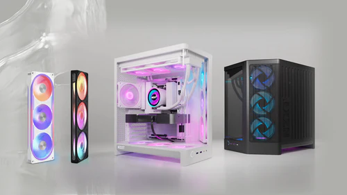
A new era. New cases. New fans. The first products from a redesigned NZXT.
A new era. New cases. New fans. The first products from a redesigned NZXT.
Article: H2 Flow Riser Card Design: Engineering Transparency & Safety Explained
We've seen recent concerns raised by the community about the PCIe 5.0 riser cable and card design in the NZXT H2 Flow. We take every piece of feedback seriously — especially when it involves safety — and we want to address this directly and openly.
We understand why this topic is sensitive. The NZXT H1 riser card issue in 2020 was a serious failure that we took full responsibility for, including a voluntary recall. That experience fundamentally changed how we approach PCB design, validation, and quality control. The H2 Flow riser card was engineered from the ground up with those hard-learned lessons applied at every stage.
Here's what our engineering team has confirmed, and what we're doing to ease concerns.
The root causes of the H1 riser card issue were that the screw mechanically interfered with the PCB screw hole, and a power trace was routed too close to that hole. Under certain assembly conditions, the screw could bridge the power trace to ground, creating a short circuit that led to thermal events.
For the H2 Flow riser card, we eliminated both of those failure modes entirely. The H2 Flow PCBA uses a shoulder standoff design that physically prevents any contact between the screw and the inner wall of the PCB screw hole. There is a defined gap — the screw cannot reach the PCB material. Additionally, no power traces are routed anywhere near the screw holes. Every copper layer surrounding the screw holes is exclusively ground plane.
The PCB stack-up near the screw holes tells the full story: every internal layer — TOP, L2, L3, L4, L5, and BOT — is connected to ground. The PCB surfaces use a black solder mask. Even in a worst-case scenario where the solder mask was somehow compromised, the exposed copper underneath is ground. Ground to ground does not create a short circuit. There is no power path to bridge.
To verify this by testing rather than design alone, we conducted destructive testing using oversized screws, tightening beyond normal spec to determine whether a short circuit could be induced under any circumstances. Before screw installation, GND and Power both measured open circuit (O.L), confirming no pre-existing short. After tightening the oversized screw, GND and Power remained open circuit. Even with the screw holes enlarged and the surface scratched, no short occurred. The GPU continued to function normally throughout. The design holds up not just in theory, but under deliberate abuse.
You may notice the absence of a screw pad in some reviews — a visible ground plane ring — around the PCB screw holes. This is because the units some reviewers received are early DVT (Design Validation Test) samples, not retail or mass production units. To provide some context on our development stages: DVT (Design Validation Test) is an early engineering phase where we validate the core design; PVT (Production Validation Test) is the final pre-production phase where the design is locked and manufacturing processes are confirmed; and MP (Mass Production) is what ships to customers.
We have confirmed with our manufacturing partner that all H2 Flow units produced after PVT, including all mass production units, are designed with the screw pad present as intended. This is not a retail product issue.
To be clear: even on the early DVT sample, the absence of the screw pad does not create a safety issue. The screw pad provides a visible ground connection at the surface — but because all underlying copper layers are already ground, the electrical safety margin remains fully intact. The screw pad is a best-practice design feature, not a safety-critical one in this specific PCB layout.
Physical isolation. The shoulder standoff design creates a mechanical gap between the screw and the PCB hole — the screw cannot contact the PCB material. Ground-only copper near screw holes. All six copper layers surrounding the screw holes are ground plane. No power or signal traces exist in this region. There is nothing to short against.
No H1 failure mode present. The two conditions that caused the H1 issue — screw-to-PCB interference and proximity of power traces to the screw hole — have been completely eliminated.
Verified by destructive testing. The design was stress-tested with oversized screws, enlarged holes, and scratched surfaces. In every scenario, GND and Power remained open circuit with no short induced and no impact to GPU function.
Being open with our community matters to us, and that means showing our work rather than asking anyone to simply take our word for it. We will be publishing additional technical documentation, including detailed cross-sectional diagrams, so that anyone who wants to verify our claims can do so independently.
If you have specific technical questions about the H2 Flow riser card design, please reach out to our support team — we'll get our engineers involved directly. We're not hiding from this conversation, and we'll continue to provide updates along the way.

40 Years of Tech and One Legendary Stick (Ft. DaPoets) - NZXT Podcast 224

NZXT x Intel Club July 2026 Giveaway

Top 500 Ana to Full Time Streamer and Hardcore Raver (Ft. Marlea) - NZXT Podcast 223
Small Scale, Massive Impact: Exploring Small Form Factor and Mini-ITX PCs
NZXT CAM 4.76.1 – Bug Fixes & Firmware Updates
At NZXT, we make PC gaming easy and fun . Whether you’re building your dream setup or going hassle-free with a prebuilt, we’ve got you covered with quality components and expert support.
Unable to load help articles. Please try again.
No help articles found for “' + query + '”
Showing Help Center results for “' + query + '”
規格
- 設計改進
- 肩墊設計、螺釘與PCB孔隔離
- 電源路徑
- 遠離螺絲孔的電源路徑,銅層用於接地平面
來源連結
規格與發布資訊引用自官方來源;本文評析為本站原創。
自 NZXT 的新設計以來,我們見證了全新的機箱和風扇的推出。H2 Flow Riser Card 是這一重新設計的第一批產品之一,它在工程透明度與安全方面進行了重大改進。
我們理解社群對 PCIe 5.0 起伏卡和卡設計的關注。這一產品的開發基於過去的經驗教訓,特別是關於安全性的反饋。通過徹底的設計變更,H2 Flow Riser Card 解決了 H1 起伏卡中的機械干涉問題,並且優化了電源路徑以避免短路風險。
該產品使用肩墊設計,確保螺釘不會與 PCB 螺絲孔的內壁接觸。此外,所有圍繞螺絲孔的銅層均專用於接地平面,進一步增強了其可靠性。
優點
- 解決了H1中的機械干涉問題
- 增強的安全性設計
討論區